 Sushil Singh 19 August 2026
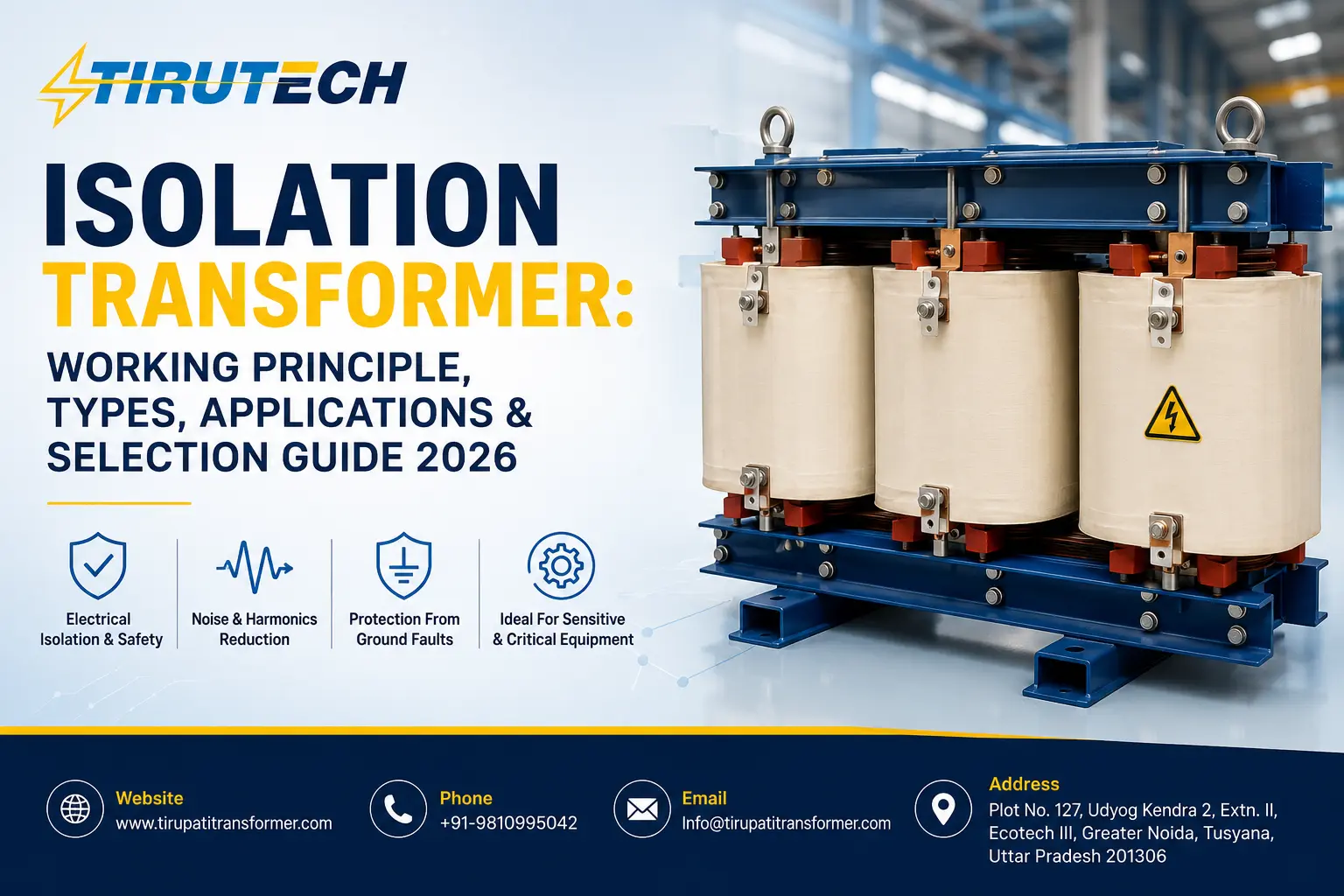
An isolation transformer is designed to transfer electrical power between circuits while providing electrical separation, or galvanic isolation, between the input and output. Unlike conventional transformers that are primarily selected for voltage conversion and power distribution — such as a distribution transformer — this type is commonly used where electrical separation, equipment protection, noise attenuation, and controlled grounding are important.
These units are used in industrial control systems, sensitive electronic equipment, medical environments, laboratories, data centers, automation systems, and other applications where the quality and safety of the electrical supply are important.
This guide explains the working principle, types, applications, benefits, sizing considerations, and how it differs from conventional transformer types.
What Is an Isolation Transformer?
An isolation transformer is a unit in which the primary and secondary circuits are electrically isolated from each other. Electrical energy is transferred between the windings through electromagnetic induction rather than through a direct conductive connection.
Many such units are designed with a 1:1 turns ratio, meaning the primary and secondary voltages are approximately the same under rated conditions. The main purpose in such a design is therefore electrical isolation rather than changing the voltage level. However, they can also be manufactured with different voltage ratios when an application requires both voltage transformation and electrical separation.
Key Characteristics
- Galvanic isolation between primary and secondary circuits
- Separate primary and secondary windings
- Often designed with a 1:1 voltage ratio
- Available in single-phase and three-phase configurations
- Can be designed with electrostatic shielding for improved noise attenuation
- Available in dry-type and, for suitable applications, oil-filled constructions
- Can be customized according to load, voltage, frequency, insulation and installation requirements
How Does It Work?
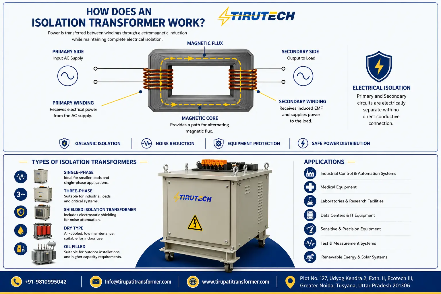
The working principle is based on mutual electromagnetic induction. When AC voltage is applied to the primary winding, it produces an alternating magnetic flux in the core. This changing magnetic field induces an electromotive force (EMF) in the electrically separate secondary winding. Because there is no direct conductive connection between the two windings, power transfers magnetically while maintaining electrical separation.
1. Primary Winding
Receives electrical power from the incoming AC supply.
2. Magnetic Core
Provides a low-reluctance path for the alternating magnetic flux produced by the primary winding.
3. Secondary Winding
Receives the induced EMF from the magnetic field and supplies power to the connected load.
4. Electrical Isolation
The primary and secondary circuits remain electrically separate — this separation is the defining characteristic of the design.
What Is a 1:1 Isolation Transformer?
A 1:1 unit has approximately the same number of turns on the primary and secondary windings. For example, an input of 415 V AC produces an output of approximately 415 V AC — the voltage is not intentionally stepped up or down. Instead, the unit provides electrical separation between the source and load, which can be particularly useful when the objective is to isolate sensitive equipment from certain disturbances or to establish a separately derived secondary circuit.
Why Is Electrical Isolation Important?
Electrical isolation can provide several system-level benefits when the unit is correctly specified and installed.
1. Reduced Risk From Certain Shock Paths
An isolated secondary can prevent a direct conductive path from the source side to the load side. However, this should not be considered a standalone shock-protection device — proper grounding, bonding, insulation, protective devices, and application-specific electrical safety practices remain essential.
2. Common-Mode Noise Attenuation
A suitably designed unit can reduce certain common-mode electrical disturbances between the source and load. For highly sensitive electronic systems, additional design features such as electrostatic shielding, filtering, or dedicated power-conditioning equipment may be required.
3. Reduction of Ground-Loop Problems
Isolation can help address unwanted circulating currents associated with certain grounding arrangements and ground-loop conditions. The effectiveness depends on the complete system grounding and bonding architecture.
4. Protection of Sensitive Equipment
Isolation can help separate sensitive loads — control systems, instrumentation, laboratory equipment, automation systems, communication equipment — from disturbances originating on the upstream electrical system.
Types of Isolation Transformers
These units can be classified according to phase, construction, cooling method, shielding, and application.
Single-Phase
Commonly used for relatively small loads and individual equipment — laboratory equipment, electronic equipment, control panels, instrumentation, testing equipment, and small industrial machines.
Three-Phase
Designed for larger industrial and commercial loads such as industrial machinery, automation systems, motor-control systems, production lines, VFD-related applications, and industrial control panels. Rating and winding configuration should be selected according to the actual electrical load, in the same way capacity is matched for a power transformer serving a larger industrial system.
Dry-Type Construction
Uses an air-based or solid-insulation system instead of liquid insulation — commonly considered for indoor installations, control rooms, commercial facilities, data centers, laboratories, and industrial automation areas. Advantages can include simplified installation and reduced liquid-related maintenance, similar to the benefits seen with a standard dry type transformer.
Oil-Filled Construction
Uses insulating liquid for electrical insulation and heat transfer. It can be considered for higher-capacity or outdoor industrial installations where the cooling and insulation requirements justify liquid-filled construction. Installation must account for fire safety, oil containment, ventilation, maintenance, environmental requirements, and applicable electrical standards.
Electrostatic Shielded Design
For applications where electrical noise is a major concern, an electrostatic shield can be incorporated between the primary and secondary windings to reduce capacitive coupling of high-frequency common-mode disturbances. This can be useful for sensitive electronic equipment, instrumentation, medical systems, and laboratory applications. Actual noise attenuation depends on construction, shielding, grounding, frequency spectrum, and the surrounding electrical system.
Industrial Applications
Medical Equipment
Used in certain medical electrical systems where patient and equipment safety requirements demand carefully controlled electrical arrangements. Medical installations are subject to specific standards, so the unit must be selected according to the applicable regulations.
Industrial Control Panels
Control systems often contain PLCs, sensors, instrumentation, and other sensitive electronics. Isolation can help electrically separate these systems from upstream electrical disturbances.
VFD and Motor-Drive Systems
Variable frequency drives can generate electrical disturbances and harmonics. An appropriately designed unit can provide isolation and, depending on construction, help address certain common-mode disturbances — though it should not automatically be considered a complete harmonic-filtering solution.
Data Centers
Isolation units may be used as part of an overall power-quality and electrical-distribution strategy protecting servers, networking equipment, and critical infrastructure.
Laboratory and Testing Equipment
Isolation can help separate sensitive measuring and testing instruments from unwanted disturbances on the upstream electrical network.
Automation and Instrumentation
Industrial automation systems — PLCs, sensors, controllers, drives, and communication systems — can benefit from isolation where electrical separation and power-quality management are important.
Isolation Transformer vs Distribution Transformer
| Parameter | Isolation Transformer | Distribution Transformer |
|---|---|---|
| Primary purpose | Electrical isolation | Power distribution and voltage transformation |
| Typical voltage ratio | Often 1:1 | Usually designed for voltage step-down |
| Primary-secondary isolation | Yes | Designed according to the distribution system |
| Main application | Sensitive/critical loads and electrical separation | Industrial, commercial and utility distribution |
| Noise attenuation | May provide common-mode attenuation depending on design | Not normally the primary function |
| Typical installation | Equipment, control systems, laboratories, critical loads | Distribution networks, plants and commercial facilities |
| Design priority | Isolation, insulation and application-specific protection | Efficiency, voltage regulation and distribution performance |
The correct choice depends on the electrical system — an isolation unit should not automatically be substituted for a conventional distribution transformer, because the two have different design objectives. For a closer look at how distribution units compare with other constructions, see our guide on Oil Filled vs Dry Type Transformer.
Isolation Transformer vs Step-Down Transformer
The key difference is the primary purpose. A step-down transformer is designed mainly to reduce voltage — for example, 11 kV to 415 V. An isolation unit is commonly designed with a 1:1 ratio, such as 415 V to 415 V, with electrical separation as the main objective rather than voltage reduction. That said, a transformer can be engineered to provide both voltage transformation and galvanic isolation when the application requires it — similar to how a compact substation combines multiple functions into a single integrated package.
How to Select the Right Isolation Transformer
Selecting the right unit requires more than simply matching the voltage.
- Determine the load: Calculate connected and expected operating load, including continuous load, intermittent load, motor loads, electronic loads, inrush current, and future expansion.
- Select the kVA rating: The unit should have sufficient capacity for the actual load under expected operating conditions — don’t select solely from the connected kW value without considering power factor and starting/inrush characteristics.
- Check input and output voltage: Specify primary voltage, secondary voltage, frequency, required voltage ratio, and tap requirements if applicable.
- Select single-phase or three-phase: Must match the electrical system and connected load.
- Consider inrush current: Motors, capacitors, switching power supplies, and other electronic equipment may have significant inrush current that should be evaluated alongside normal operating load.
- Evaluate noise requirements: Determine whether electrostatic shielding, special winding arrangement, low capacitance coupling, or additional filtering is needed.
- Select the appropriate construction: Choose dry-type or liquid-filled based on indoor/outdoor location, ambient temperature, ventilation, fire-safety requirements, and space availability.
- Check applicable standards: Design and testing should follow the standards applicable to the specific unit and installation, such as IEC 61558-2-6, the international standard covering safety isolating transformers for general applications.
Sizing Example
Suppose an industrial control system has a connected load of 18 kW at a power factor of 0.9. Approximate apparent power is calculated as:
kVA = kW ÷ Power Factor → 18 ÷ 0.9 = 20 kVA
The final rating should not automatically be selected as exactly 20 kVA. The engineering assessment should also factor in continuous loading, inrush current, ambient temperature, duty cycle, harmonic content, future expansion, and required operating margin. For an actual project, sizing should be finalized from the complete load schedule and electrical design.
Advantages
- Galvanic isolation between electrical circuits
- Reduced direct conductive coupling between source and load
- Potential reduction of certain common-mode disturbances
- Support for sensitive equipment protection strategies
- Availability in single-phase and three-phase designs
- Customizable voltage and kVA ratings
- Suitable for industrial and specialized applications
- Can be designed with electrostatic shielding where required
Limitations
This design is not a universal solution for every power-quality or safety problem:
- Introduces normal transformer losses
- Requires physical installation space
- May have voltage regulation/drop under load
- Does not automatically eliminate all harmonics
- Does not replace proper grounding and protective equipment
- Incorrect sizing can result in overheating, voltage drop, or nuisance tripping
- Specialized applications may require additional filtering or power-quality equipment
Frequently Asked Questions
Q1. Where is an isolation transformer used?
Ans: These units are used in industrial control systems, sensitive electronic equipment, laboratories, instrumentation, data centers, and medical electrical systems where electrical separation is required.
Q2. What is a 1:1 isolation transformer?
Ans: A design with approximately equal primary and secondary turns, generally intended to maintain approximately the same nominal voltage while providing galvanic isolation.
Q3. Does an isolation transformer reduce voltage?
Ans: Not necessarily. A typical 1:1 design maintains approximately the same voltage, though these units can also be built with different turns ratios when voltage transformation is required.
Q4. Does an isolation transformer remove harmonics?
Ans: Not necessarily. It can provide isolation and may attenuate certain common-mode disturbances, but should not automatically be treated as a harmonic filter — mitigation depends on the design and the overall electrical system.
Q5. Does an isolation transformer save electricity?
Ans: Energy saving is not the primary purpose. Like any transformer, it has core and winding losses; the main benefits are electrical isolation and, depending on design, power-quality advantages.
Q6. Can it be used outdoors?
Ans: Yes, suitable constructions can be designed for outdoor installations depending on required capacity, enclosure, insulation system, cooling method, and applicable safety requirements.
Q7. What size do I need?
Ans: Required size depends on connected load, power factor, inrush current, operating duty, ambient conditions, and future expansion — sized in kVA rather than matched directly to connected kW.
Why Choose Tirupati Transformer?
Selecting the correct isolation transformer requires understanding the complete electrical application rather than picking a standard rating alone. Tirupati Transformer’s engineering team can evaluate requirements such as capacity, primary and secondary voltage, single-phase or three-phase configuration, dry-type construction, insulation, cooling, shielding, and indoor/outdoor installation as part of a custom or turnkey project.
If you’re planning an industrial project and need to evaluate an isolation requirement alongside your broader transformer needs — including servo voltage stabilizers or a compact substation for the same facility — get in touch with our engineering team to discuss your specifications.
Conclusion
An isolation transformer provides electrical separation between the primary and secondary circuits while transferring power through electromagnetic induction. Although many such units use a 1:1 ratio, they can also be designed with other voltage ratios when both isolation and voltage transformation are required. The right selection depends on kVA rating, voltage, phase, frequency, load characteristics, inrush current, insulation, installation environment, noise requirements, and applicable standards — proper sizing and engineering evaluation remain essential for reliable and safe operation.